Tool axis control: Deburring
Introduction
This topic will explain the options found in the Tool axis control tab of the Deburring operation.
Tool axis control
The Tool axis control tab allows you to set the tilt of the tool, angle limits, and clearance values.
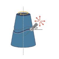
Tilting
-
Machining type - defines the degree of freedom when tilting the tool.
-
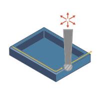
3 axis - This option should be used with 3-axis machines. The user must specify a single tool axis direction. When the tool cannot reach a certain area, the toolpath is clipped. Non-machined edges might occur.
-
Important: Ball mill cutters with a conical shaft have limitations when machining vertical edges, and the tool axis must be 3-axis. Due to its shape, the toolpath is clipped. As a result, the toolpath will probably only be on the edges of shallow areas.
-
4 axis (rotary) - This option creates 4-axis rotary toolpaths. The tool axis is orthogonal to the selected rotary axis and always points directly towards the rotary axis. Use this option when you have a 4-axis machine with no y-axis offset.

-
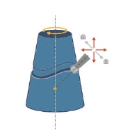
4+1 axis (autotilt) - This option creates 4-axis simultaneous output and keeps only the (side) tilt angle constant. The system tries to keep the tool orthogonal to the edge. A rotation axis must be specified as reference, and a fixed angle.
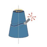
Note: As an example, if you have a cylindrical part aligned in the +z direction and mounted on a rotary C table, you can lock the B-axis or A-axis with the fixed angle. This allows the rotary table to rotate back and forth which enables the tool to be orthogonal to the edge while A and B remain fixed. There is also an option called Point tool to rotary axis which locks the tool axis to the rotation axis. This prevents the tool from tilting back and into the lead direction.
-
3+2 axis - This option can only be used on a 5-axis machine. It is similar to 5-axis tilting. The only difference is that the system tries to keep the tool axis fixed as much as possible.
Note: Remember that collision checking can change the tilting to 5-axis simultaneous tilting when necessary to avoid collisions.
-
5 axis (simultaneous) - This option can only be used on a 5-axis machine. Two options are available:
-
Strategy - When using the 3+2 axis, and 5 axis (simultaneous) machining types there are two strategy options available:
-
Normal to contour - The system tries to keep the tool orthogonal to the edge and the tool axis in the bivector between the two surfaces of the edge. There is only the initial tilting. Collision control may alternate this orientation.
Fixed angle to axis - This option keeps the tool axis at a fixed angle to an axis, but with the possibility to tilt away if necessary. Collision checking can tilt the tool away to avoid collisions. We expect this option to be the most used option because it provides minimal tilting with full flexibility and collision avoidance.
-
-
Axis - The user can select the rotational axis for 4-axis control and the main axis for 5-axis control. The axis can be defined either by using a start point and end point or by using a base point and direction. The base point can be the center or a user-defined point. The direction can be selected from one of the 3 main axes or a user-defined one.
- Tilt range - When using the 3+2 axis, and 5 axis (simultaneous) machining types this option allows you to specify the range of allowable tilt with the lead angle being relative to the cutting direction.

 - No tilt range is specified.
 -
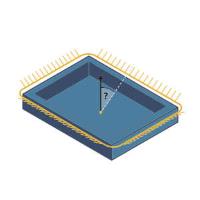
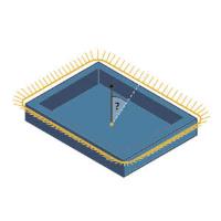
Enter Min and Max angles to specify the angle of each of the two conical boundaries to keep the tool between.
-
Enter Min and Max angles to specify the angle of each of the two conical boundaries to keep the tool between.
| Min. |
Max. |
|
|
 |
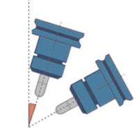
- Point tool to rotary axis - When using 4+1 axis (autotilt) for the Machining type, this option forces the tool to tilt through the rotary axis, and it can no longer tilt in the lead/lag direction.
 b
- The tool is not forced to point to the rotary axis. -
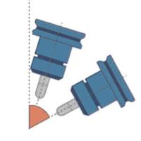
The tool is forced to point to the rotary axis.
b
- The tool is not forced to point to the rotary axis. -
The tool is forced to point to the rotary axis. - Fixed angle - When using 4+1 axis (autotilt) for the Machining type, this option allows you to set the tool at a specific angle. The value entered is angle between the tool tip vector towards the spindle direction and the rotary axis vector.

Note: As an example, 4-axis machines sometimes have a fixed tilted head, for example a 45 degree head. In this case, the spindle direction is, for example, tilted 45 degrees towards the rotary axis vector, which means the locked axis value must be set to 45 degrees.
Tip: To reduce rotary axis motion, you can use a 5-axis machine and set the toolpath output to 4-axis with a fixed 5th angle. This fixes one of the rotary axes for the whole toolpath.
-
Tilt angle - The tool is tilted from a fixed axis (Z, Y or X) towards the surface normal direction with a specific angle.
Tip: This method is recommended for rotational components in a 4-axis machining process.
-
Lead angle to cutting direction - When using the 3+2 axis, and 5 axis (simultaneous) machining types with a Fixed to main axis Strategy, this angle defines the lead/lag angle of the tool axis. This angle lies on the plane created from the normal of the edge and the vector of the toolpath segment.

-
Maximum angle step - When using the 3+2 axis, and 5 axis (simultaneous) machining types this sets the maximum allowed angle change between two consecutive toolpath positions.

Important: This option also defines the resolution of the maps used for collision checking. That means that collisions are checked every 3 degrees (angle change of the tool axis). A 3 degree step angle is usually enough, depending on the model geometry and the tool geometry. If there are sections along the contour where the tool is very close to the geometry, a 3 degree step might be too large to find a solution and a finer resolution should be used (2 degrees, 1 degree or even smaller). This parameter has a big impact on the computing speed and can cause a failure if there are sections where the solution exists only for a couple of degrees in the orientation of the tool.
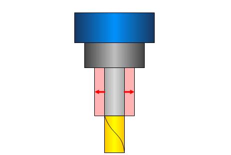
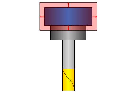
Clearances
The available Clearance values define the clearance for the Shaft, Arbor, and Holder.
|
|
|
|---|---|
|
|
|

|
|
|
Important: These values should be greater than the allowance being left on the surfaces.